Original article by
HDMI is sensitive to a number of manufacturing decisions and installation conditions that can result in system failures.
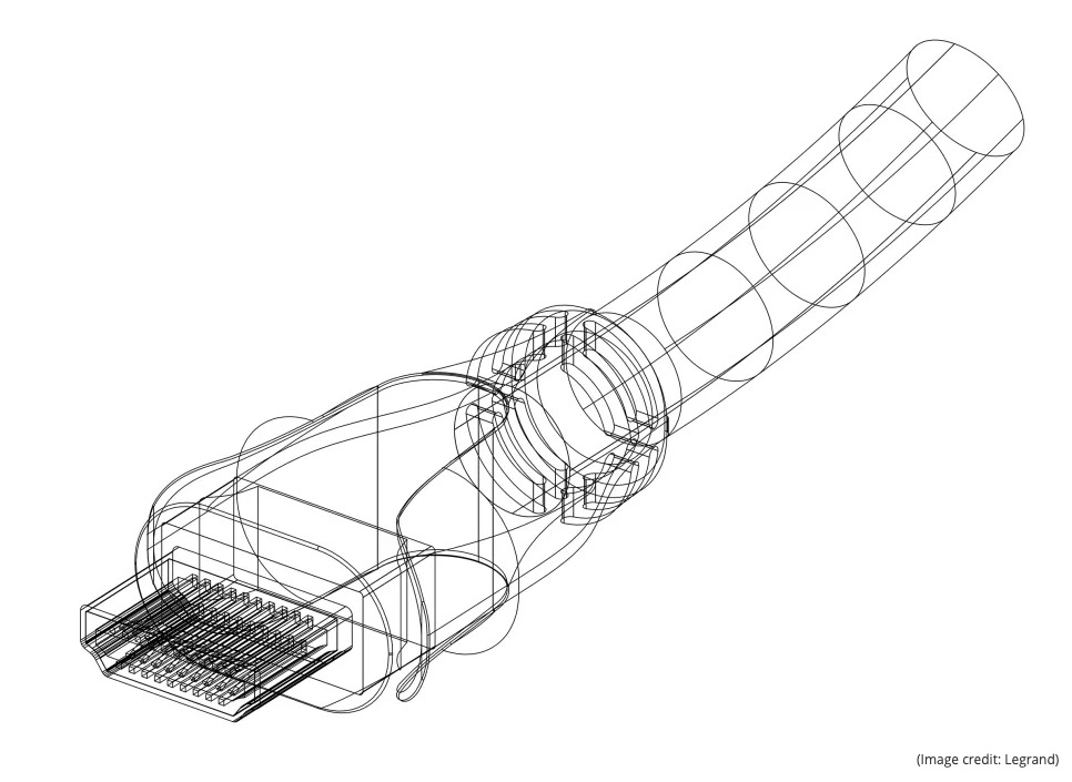
High Definition Multimedia Interface (HDMI) is the most used connector in AV today. The annual global market for cables alone is valued at more than $2.5 billion and has an expected combined growth rate exceeding 5 percent over the next several years. However, since its introduction in 2005, HDMI has saddled AV professionals with numerous complications. It is sensitive to several issues resulting from manufacturing decisions and installation environmental conditions, including voltage inefficacies, improperly powered cable assemblies, link bandwidth, and more.
Starvation and Failure
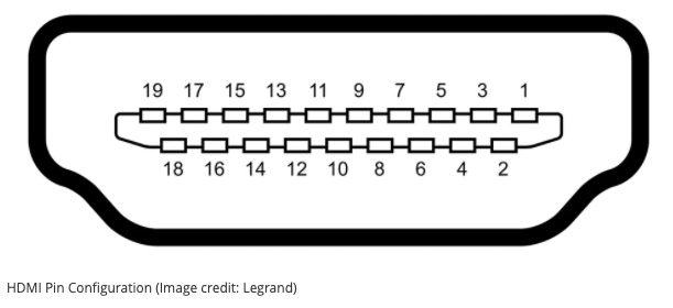
This transition minimized differential signaling (TMDS) conditioned AV transport method delivers red, green, blue, and sync (clock) payloads over four shielded twisted-pair wires embedded in a 19-conductor cable. Each of these pins plays a role in transporting signals, but for the purpose of this article, our focus is on Pins 18 and 19. Pin 18 is the source for the power bus that allows for E-EDID data transfer across the display data channel (DDC), while Pin 19 is the hot plug detect (HPD) pin.
Nearly a decade ago, it was noted that there was potential for HDMI failure because of voltage “starvation.” In the simplest of cases, voltage drop across an excessive length of copper wire can drive the HPD voltage below the 5V at 55mA +/-5 percent threshold of the HDMI standard. A 24AWG copper wire is .0201 inches in diameter and presents 0.026 ohms per foot of cable in DC resistance. For a 50-foot cable, the total loop DC resistance of Pins 18 and 19 in the circuit (shown mathematically, 0.026x50x2x2) is 5.2 ohms. Ohm’s Law tells us that the voltage drop across a resistor is described by the formula V=IR, where I=0.055A and R=5.2Ω. Therefore, Vdrop = (0.286V). An online calculator confirms the voltage drop at -5.65 percent, with a DC voltage drop of 0.28V across the cable.
Right away, we see this link may fail if the source device is limited to the minimum requirements of the HDMI standard, which isn’t considered a failure. The result is that the longer the HDMI cable, the greater the wire gauge a manufacturer must use to have any confidence the link will work. At some point, the cable will not only become unwieldy and inflexible but will also increase the likelihood that the payload will be adversely affected by the electrical characteristics of the cable itself.
Unexpected Issues
Often, when an active solution or passive cable doesn’t perform as expected in a system, its design or build quality is immediately suspect. However, it’s possible for the cable to be well designed and appropriate for its task—but associated components can’t provide the power or signal integrity necessary for optimal performance. There is a lot to uncover here that goes beyond the scope of this article, but what’s been discovered is that processing more data requires more power. This holds true for both active optical and active copper solutions.
A good example of this is when a laptop computer is connected to a 4K LED flat panel via a 50-foot active optical cable that is rated for payloads up to and including 4K/UHD 2160p in a 4:4:4 RGB color space. This system works perfectly for 1080p content, but when trying to display 4K content, there’s no picture or the picture is distorted. What happened?
When the active optical cable is transporting an FHD payload, its vertical cavity surface-emitting lasers (VCSEL) must flash on and off to communicate each bit sent across the fiber link. There are four VCSELs in an active optical HDMI cable. They are used to convert TMDS lanes 0, 1, 2, and 3 from electrons to light-based transport. This allows for significantly greater link lengths. Additionally, this improves signal fidelity, since fiber is essentially impervious to RFI and EMI, which can dramatically affect the payload in copper links.
In an FHD system, the lasers will fire more than 3.7 billion times combined each second. Breaking this down, a single VCSEL is pulsing on and off more than 1.2 billion times per second. The clock link must fire just as quickly to keep things in sync, so this is a total of 4.8 billion pulses each second across the four optical lines.
A 4K signal operates at 2160 visible vertical pixels x 3840 visible horizontal pixels. The uncompressed bandwidth of this exchange is 14.92 Gbps. (14.92Gbps is 2160x3840x60 frames/sec x 8 bits per pixel x 3 for each of the red, green, and blue links x 1.25 for the 8b/10b overhead associated with the TMDS conditioning used in HDMI communication.) Each of the lasers is pulsing four times faster for a 4K payload—nearly 5 billion times per second. Clearly, the power supply on Pin 18 must work much harder to power the additional pulses. It’s entirely possible the source just can’t muster this kind of power, despite being rated for UHD and meeting the HDMI standard requirements.
Power Variability and Link Failure
The plot thickens as we move from a standard FHD to a payload that is HDR, 4K/UHD, or both. It stands to reason that we are asking the system to process many more bits of information. The more bits we send, the more time it takes for all of them to get through the system unless the data rate is increased.
With many of the systems in use, there is a maximum data rate built into the format. HDMI 1.4 has a maximum data transfer rate of 10.2Gbps, while HDMI 2.0 is 18Gbps. This is where clock stretching comes in—the display can tell the video source to slow down a bit. Most, but not all, HDMI sources support clock stretching. Clock stretching often presents HDCP-protected content issues when HDBaseT extenders are used; it causes a delay that can exceed the limits of the source and stops HDCP content if the EDID isn’t received in time, further consuming more current from the 5V supply.
Additionally, stressing the source device’s HPD power supply may overwhelm the IC buffer in a less than optimal product design, or possibly cause crosstalk noise between the SLC clock and the SDA data lanes. The ACK command may then be interpreted incorrectly as a follower device holding the SDA line LOW and causing the data exchange to stop and no image will be displayed.
Measuring the power output capability of several source devices under test from Pin 18 helps to better understand the chaotic nature of link failure in extended HDMI solutions. These tests revealed there is great variability in the available power, which isn’t too surprising considering there’s no incentive for device manufacturers to overbuild once they meet the HDMI standard requirements. Without testing each source, there’s no way to know how the power supply of an HDMI source will behave, which is time-consuming and delicate.
The Future of HDMI
These failures are just beginning to be examined and addressed. Currently, there are not many options to resolve them.
To overcome voltage starvation, a voltage inserter can be used, which breaks the connection of Pin 18 at the source and substitutes an external power supply in place of the supply built into the device. However, a voltage inserter won’t cure all failures. Sometimes, active signal reinforcement is required. In those situations, an active in-line HDMI extender may be needed. In-line extenders may be powered from Pin 18 or from a dedicated device power supply. The challenge of in-line extenders is that they work best when positioned at some arbitrary mid-point between the source and the sink, which can be difficult in plenum or full conduit installations.
Creating and building an optimal HDMI extension design requires analyzing and evaluating the capabilities of active devices, and anticipating the needs that will have to be met to work dependably with today’s content and with the 4K, 8K, wide-gamut color, HDR payloads of tomorrow. New extension devices are already making strides in this area. They require less power, exhibit less variation in power demands as mapped to payload complexity, and are more stable under all conditions.
In addition, the new HDMI 2.1 specification increases permissible maximum data rates from 18Gbps to 48Gbps. There is also a powered cable assembly (PCA) addendum to the HDMI 2.1 spec that calls for an auxiliary power supply for active cables. Under this new specification, advanced sources may deliver enough power for the active cables designed to support the enhanced bandwidth of next-generation connectivity, but not for powering external peripheral devices. This new HDMI standard relies on manufacturers disclosing standardized support capabilities, but keep in mind that most manufacturers aren’t even close to understanding the limitations of HPD bus power in their current product lineup.
Creating dependable, predictable, and efficient solutions that support creative system design that anticipates the next generation of video system performance requires state-of-the-art testing techniques to analyze and evaluate all the contributions of the physical layer link.
![]() The complete white paper Ghost in the HDMI Machine: Advanced Extension Challenges & Solutions can be downloaded here.
The complete white paper Ghost in the HDMI Machine: Advanced Extension Challenges & Solutions can be downloaded here.